|
|
   |
LIFTERS
 |
 |
 |
 |
 |
|
|
||||
The last weeks I have built a
series of Lifters to test some ideas.
I discovered two things :
- a simple foil lifter (one third of the standard one) has a different thrust
according to the position of the leads: if + and - are connected both at
one end of the foil the thrust is weak. If they are connected oppositely
The building of my first Lifter
Thanks to Jean
Louis Naudin for his wonderful work which brought the opportunity to
the world wide group of new science pioneers to replicate the very basis
of Thomas Townsend brown's works. And thanks again to those who helped me
with such a goodwill, and are improving the group process giving good advices
in the jln
and Lifters
groups.
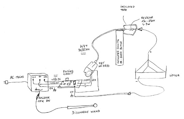
Though my past studies in electricity and electronics are 14 years behind me, I succeeded in building my first High Voltage power supply (30kv or a little more) with a FBT and a small pulsing circuit. Please see the "How to build a HV power supply" page in this website, where you will find various models of HV power supplies, including mine.
After I set up all the components, I made a first test: nothing happened. I had forgotten a connexion with the timer. Then second try: a sound, the lifter moved.... and the two enameled wires of the lifter crossed: beautiful violet sparks!... and beautiful shortcut. The transistor is now dead, and certainly the timer... so, good lesson for the next time: to be very careful so that the wires don't cross at any moment, and place them at a good distance, the upper one must not touch the ground or the experimental surface.
I built the Lifter according to the model given by American antigravity, a triangle made of balsa wood and aluminium foil. See http://tventura.hypermart.net/Construction-Guide.pdf
Other very useful files from American Antigravity are also available. You can download them directly from here (below) or go to American antigravity /Lifters/Construction guides/.
- Trouble
shooting guide
- Frequently
asked questions
- Required
materials
- Safety
guidelines
- Testing
guide
- Testing
guide-GRA3
- Construction
guide
And please visit the Blaze Lab Electronics website, which contains many important informations to increase the lifters thrust (also from other lifter testers), as well as various different interesting lifter shapes.
In the JLN lifter log book, you will find many other informations concerning the world wide lifter experiments, and at http://jnaudin.free.fr/html/liftbldr.htm you'll find many other shapes tested by numerous experimenters as well as by Jean Louis Naudin... Enjoy!
I finally changed only the transistor BU508AW it was really dead! I checked the timer with a frequency meter and it was ok, then I just adjusted the rate with the variable resistor at 15625Hz, the resonance frequency of the FBT 7839 (according to HR Diemen). I placed also a 220k 2W resistor between the HV+ cable and the lead of the lifter to avoid to burn again the transistor.
I switched on the power supply,
and then a hissing noise began.... some seconds after, the lifter jumped
from the table and stabilized in the air above the table!!!! It was really
amazing!
After many tests, I crossed again the wires, at first, nothing happened,
but the third time all was dead again. Only the 220k resistor burnt (because
2W is not enough, 4-5W is the best), but at least, as expected, it cut the
circuit and stopped the shortcut, so except a smell of burnt plastic, all
was ok.
All is working well now, and I've made some tests with new forms to study the way the extrafluid (I believe it is a fourth ether stream of particles that begin the movment) and then the air passes throught the poles of the assymetrical condenser. You can check the movement of the air with the smoke of an encens stick, then this shows you the hidden shape of your condenser. If you place your hand below the lifter, you can feel the air stream.
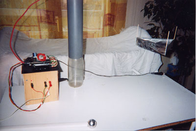
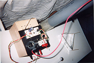
Picture 1:
A close up of my DC power supply 68v powered from the mains AC220v/50hz
with the FBT HR 7839 and the pulsing circuit. The output voltage is 30,4
kV
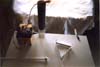
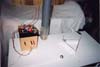
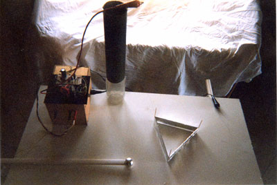
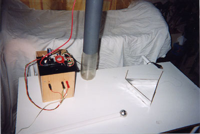
Picture
2 and 3:
My worktop
Picture 4:
The first flight !
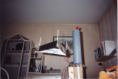
Picture 5:
Another shot of the first flight