To build a
HV Power supply
Construire une source de Haute Tension
This page gathers informations
scattered in other websites. It is designed to facilitate the building of
a HV supply to those interested in the Lifter tests. Anyway it is strongly
recommended to study the original webpages from where these informations come
from. To respect the work of those who created the electronic circuits and
of those who built them and give wise advises, their web address is always
given where the informations appear in this page. Please contact them directly
if you need more information. They will be pleased to help you. Then, if you
think your questions and the answers you received could be useful, please
forward them to me so that this page may be updated for the benefit of others.
This is a group process, and what is good for the group is good for individuals!
Please read carefully
the warnings just below!
Merci de lire attentivement les avertissements ci-dessous!
Thanks, C.D.
|
|
   |
|
Warning! Avertissement! Construire une source de haute tension est votre propre responsabilité. Les expériences de haute tension sont dangereuses et peuvent vous blesser, ou même causer la mort de personnes utilisant des pacemakers, ayant des maladies de coeur ou simplement des faiblesses cardiaques. Si vous ne connaissez que peu de choses relativement à la haute tension, l'électricité ou l'électronique, demandez de l'aide à une personne plus compétente. Soyez extrêmement prudent. Bien que les lifters puissent sembler être des jouets amusants, ils ne le sont pas! Considérez-les comme des objets d'expériences scientifiques, et soyez aussi sérieux que vous le pouvez pour vous protéger vous-même et les autres personnes qui pourraient s'approcher de vos appareils chez vous ou dans votre "laboratoire". Faites particulièrement attention aux enfants qui pourraient essayer de reproduire vos expériences lorsque vous n'êtes pas à la maison. Si vous construisez votre source de haute tension, les risques qui en découlent vous concernent. Je n'endosse aucune responsabilité relativement à ce qui pourrait se passer.
To build
a HV power supply, you will need: Note: according
to your own power supply building, some components of the following circuits
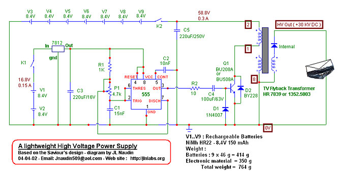
may be useless. For instance, I didn't need the 7812 voltage regulator,
for I had already 12vDC from my power supply. This component is used to
reduce the 16.8v voltage to 12v from the two batteries in the first circuit
in this page, so that it can be correctly feed the timer NE555. If you
are using a reliable DC source (powered from the mains), you may not need
the C5 condenser 220uF. But if you are not sure it is a good DC sources,
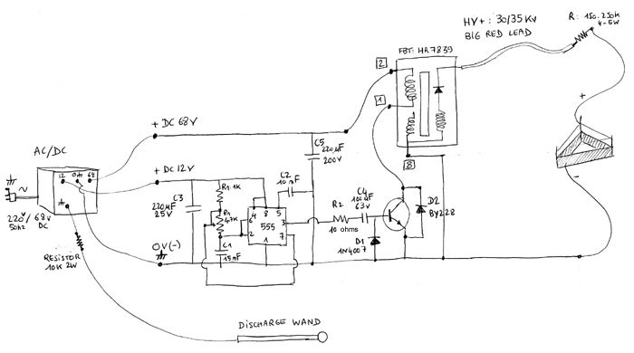
then keep it, for it will stabilize your DC source. It is necessary to place a resistor 150-250k 4-5w in case of short cut, if the lifter wires cross, so that you won't burn your transistor.
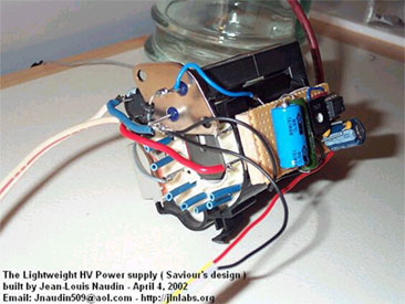
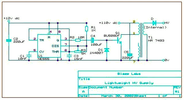
Electronic schemas The two electronic circuits below are from Saviour at Blaze Lab (http://bel.150m.com/exp03.htm). The first one has been build by Jean Louis Naudin http://jnaudin.free.fr/html/lwhvps.htm, and the second by Saviour. Please always check the orignal webpages of the schemas for the authors may have added some updates and new important advices. Saviour,
from Blaze Lab said : Concerning
the variable resistor 4.7k, I asked which value to use :
Note: HR Diemen said that the FBT 7839's resonance frequency is 15625 Hz. So you can also use a frequency meter at the output of the NE555 (without connecting the FBT) and vary the 4.7k adjustable resistor until you reach this value. If you are using another FBT, try to find its diagram e at HR, and ask them the value of the frequency. Another
technical note from Saviour ( 04-05-02 ) - from the JLN
webpage BE CAREFUL, USE EXTREME CAUTION
!!!, this device uses High Voltage, ALWAYS switch off the input and discharge
the output to the ground through 10k/2W resistor before touch it. These
plans are not intended for the inexperienced. User of this document should
be very carefull and experienced in High-Voltage electronics to try anything
out ! (...) JLN
webpage
Click here to download the FBT HR-7839 diagram (pdf 12k)
The following one is from
Blaze Electronics Lab http://bel.150m.com/exp03.htm
; it is a very lightweight one. Extract from the webpage
: Click here to download the BU508DFI description (pdf 70k)
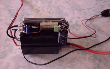
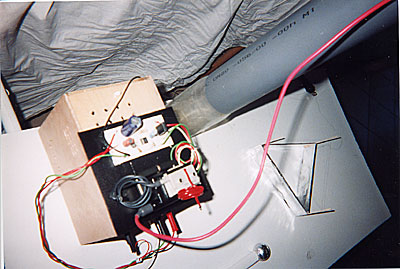
Now, the HV supply I've built : I used a DC 68v powered from the mains AC220v/50Hz, (with the first circuit in this list) from an old amplifier I found in an electronic store. Then I bought the electronic components (I didn't want to use batteries, for they need to be charged regularly), and a FBT HR7839. The metal part of my AC/DC transformer 220AC/68vDC is connected to the ground. The 0v in the latter is also linked to the ground. I have two 0v/ground outputs in my AC/DC transformer. One for the 0v of the circuit, and another one to connect directly a discharge wand. The wand is made of an hollow insulated rod, with a plastic sphere (from a deodorant stick!) coated with aluminum tape. Then the lead comming from the inside of the wand is connected to the sphere. Once you have finished your experiment, switch off your power supply and pass the spere of the wand on the + lead. You'll see/hear a little spark. Then your FBT/lifter + pole is discharge and you can touch it. But please, read carefully all the safety guidelines given by Tim Ventura concerning high voltage experiments: There is also a 150-250k 4-5w resistor between the HV+30/35kv and the positive lead of the lifter (see the drawing), so that a shortcut (thin enameled wires + and - of the lifter may cross during the experiment) won't burn the transistor. If you use a lower power, (i.e. 220k 2W), you resistor may burn. Then it will cut the circuit, which is good, but you'll have to change it after a too long shortcut. Note: I have bought recently a High Voltage Probe Fluke 80k - 40kV on Ebay, for $37.85 (plus $17.35 for shipping to France, which is still a good deal!) on www.ebay.com and the measure of the output voltage of my FBT with the HV Probe plugged in a voltmeter is 30.4kV.
Cost : Fly
Back Transformer HR7839 : 39.5E Though their exists other ways to make high voltage supplies, and certainly less expensive, this one is working well and all the components may be found easily. Except maybe for the tranformer AC220v / DC68v-DC12v, which is old and a bit rare. You can also order some high voltage supplies in the United States, at http://www.amazing1.com or even you can find some in the Ebay (bidding) website http://www.ebay.com from time to time. But you must not forget the taxes of your own country (TVA 19.6% in France) plus the customs (about 5-6%), and the mail price (it depends if you are in a hurry or not... international express and UPS are expensive, other means take weeks, and the cheapest - surface - sometimes months...). So that's why it's interesting to order from the US only if you have found a good deal and if the total price compared to what you could buy or build in your own country is less expensive. By the way, don't forget that in the States the mains is 110v/60hz and in France 220/50hz. So you'll need to buy in your own european country a transformer 220/110v but you must ask to the seller if the apparatus will work in 50Hz! But if you are skilled in
electronics, then you will certainly save time and money! Below, a request from a member of the JLN Group. If you would like to answer him, please email me and I'll forward the message :
I hope all this will be useful and that you will succeed in the building of your HV supply as well as of your first lifter. To see it flying over the table is really amazing!
|